Underground Fire Water Systems
One of the most important measures of preventive fire protection is the provision of extinguishing agents in sufficient quantities. Water is the most suitable extinguishing agent for the vast majority of fires. If supply from the drinking water network is possible, this solution is implemented. In many cases, however, an independent supply of fire water is necessary. Underground fire water tanks can be a solution here.
Advantages
for end users
High fire damage, at the same time as there is no reliable supply from the public network: in this case, fire water storage is required.
for municipalities
For new development or expanding construction or commercial properties, a decentralized fire water tank allows for reduced cross-sections of potable water supply.
Basic design
Basic protection
| Building use according to §17 of the Building Use Ordinance | Small settlement (WS) Weekend house areas (SW) | Pure residential areas (WR) General residential areas (WA) Special residential areas (WB) Mixed areas (MI) Village areas (MD) | Core areas (MK) Commercial areas (GE) | Industrial areas (GI) | ||
| Commercial areas (GE) | ||||||
| Number of full storeys | ≤ 2 | ≤ 3 | > 3 | 1 | > 1 | - |
| Number of storeys (GFZ) | ≤ 0,4 | ≤ 0,3 - 0,6 | 0,7 - 1,2 | 0,7 - 1,0 | 1,0 - 2,4 | - |
| Building mass number (BMZ) | - | - | - | - | - | ≤ 9 |
| Fire water requirement for different risks of fire spread: | m³/h | m³/h | m³/h | m³/h | m³/h | m³/h |
| small | 24 | 48 | 96 | 96 | 96 | 96 |
| medium | 48 | 96 | 96 | 192 | 192 | 192 |
| big | 96 | 96 | 192 | 192 | 192 | 192 |
DVGW Guideline W 405 determines the demand for fire water. It is to be applied for the planning and construction of specified development areas and for constructions in outdoor areas.
Property protection
According to DVGW Guideline W 405, property protection is the property-specific fire water supply for buildings with a particular fire risk that goes beyond basic protection. A distinction is made between public and non-public fire water supplies. This classification is particularly important for the building permit procedure, because requirements can only be made for the non-public fire water supply.
Storage capacity
DIN 14230 distinguishes between small (75 m3 to 150 m³), medium (from more than 150 m³ to 300 m³) and large (of more than 300 m³) fire water tanks. The withdrawal piping is defined according to DIN 14244.
Implementation
Variants
The fire water volume can be designed in two structural variants. Either by a single underground fire water tank that can hold the entire volume of fire water or by connecting several individual underground tanks. The sum of the connected individual tanks then results in the total capacity of the fire water tank.
Material
There are no restrictions on the choice of material. The fire water tank must be stable and durable against the forces acting on it.
Shape
The geometry of the fire water tank may be chosen in any way and adapted to the local conditions. The tank must be accessible for inspection and maintenance purposes and 18 tons passable. The fire water tank must be designed in such a way that the entire volume can be inspected and cleaned.
System examples
with GRP underground tank
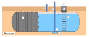
The tank can be configured very individually and thus according to customer or project requirements. The tank equipment is based on the specifications of DIN 14230 and includes, for instance, the access dome with 1 m diameter and D400 cover, an access ladder, the venting and withdrawal piping with “Storz A”-coupling made of stainless steel incl. anti-vortex plate. The tank can be filled via a rainwater base line or externally via an additional filling nozzle or directly via the manhole. Compared to an identical GRP underground tank, a 100 m³ concrete storage tank has about 25 times the weight.
- GRP tank
- Stainless steel vent piping with cover and insect screen
- Stainless steel withdrawal piping with Storz coupling form A
- Cover D400 galvanized steel
- Manhole
- Access ladder
- Anti-vortex plate
- Pumping sump
https://www.intewa.com/en/fire-water/fire-water-system-solutions/
with filling element storage in foil and suction pit
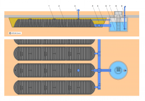
By laying the system in a foil jacket, almost any system size with a very flat structure can be realized. This saves costs for civil engineering. This special foil is an absolutely waterproof, high-strength, elastic EPDM foil without any connecting seams in one piece. The water withdrawal is done via a suction pit on the side, which is also used for maintenance and inspection. The equipment of the storage chamber and suction pit is based on the specifications of DIN 14230.
- DRAINMAX trench
- Filter fabric
- Ventilation
- Backfilling of tunnel
- Filter fabric
- Suction pit
- Ladder
- Anti-vortex plate
- Suction pipe
https://www.intewa.com/en/fire-water/fire-water-system-solutions/
Digital monitoring and multiple use of the storage volume
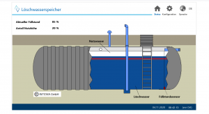
Up to now, the fill level of fire water storage tanks has only been monitored manually, if at all. This poses a major safety risk in the event of a fire, if the intended water level would no longer be available due to leakage or even unauthorized withdrawal for another application, such as irrigation. For this reason, fire water storage tanks have not been used for other applications with additional storage volume up to now. However, the use for other possible applications could provide significant advantages. For example, in addition to fire water storage, the storage tank is also ideally suited for drinking or cooling water emergency storage. If the additional volume with rainwater is to be used for irrigation, as service water or attenuation volume, a corresponding rainwater filter and an overflow must be planned.
With the I-CONNECT technology, fire water systems can now be remotely monitored. The system uses the symbiosis of hardware, the system buried in the ground, and a control system and software, which is clearly displayed via an interface on a PC, tablet or smartphone or offline via a USB connection. Plant operators are now able to control or monitor their system at any time. For example, the current fill level can be displayed via the continuous documentation of this data or alarms can be activated if the fill level is too low.
https://www.intewa.com/en/products/i-connect/control-unit/fire-water/
Legal regime
- DVGW Guideline W405 2008 Supplying fire water from the public drinking water supply system
- DIN 14230:2012 underground fire water tank
- DIN 14244:2003 fire water suction connections - above surface and below surface


